

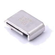


Bourns MF-SM150/33 Resettable Fuse 1.50A 33V SMD
Bourns MF-SM150/33 radial leaded resettable fuse, 1.50 A hold current, 33 V maximum voltage, 插件 package. Self-resetting after the fault is cleared, no replacement needed.
The MF-SM150/33 is a surface-mount resettable fuse that carries 1.50 A continuously and withstands 33 V maximum. The body measures 8.00 to 9.50 mm long, 6.71 mm wide and 3.0 mm high, with tin-plated brass terminals, and it suits reflow soldering. UL recognised, AEC-Q200 qualified, RoHS compliant. Commonly used for overcurrent protection on 24 V automotive modules, industrial power supplies and communication equipment.
Category:Resettable fuse / SMD, SMD package
Voltage:33 V; Current:hold 1.5 A; trip 3 A.
Specifications
| Parameter | Value |
| Hold current | 1.5 A |
| Trip current | 3 A |
| Maximum voltage | 33 V |
| Maximum fault current | 40 A |
| Initial resistance | 0.06 Ω |
| Post-trip max resistance | 0.23 Ω |
| Trip current / time | 8 A / 5 s |
| Dissipated power | 1.9 W |
| Package | SMD package |
Temperature Derating
| -40℃ | -20℃ | 0℃ | 23℃ | 40℃ | 50℃ | 60℃ | 70℃ | 85℃ | |
| Hold current (A) | 2.27 | 2.01 | 1.76 | 1.5 | 1.25 | 1.13 | 0.99 | 0.87 | 0.68 |
| Share of 23 °C rating | 151% | 134% | 117% | 100% | 83% | 75% | 66% | 58% | 45% |
Product Description
What this product is
The MF-SM150/33 is a polymer resettable fuse placed in series between a supply and its load to limit current. Its 1.50 A hold current suits relays, solenoid valves and fans on a 24 V rail. Above 3.00 A the internal material expands with heat, resistance climbs and the loop current is held to a low value. Once the fault is cleared and the part cools, it conducts again by itself.
Dimensions and appearance
Surface-mount package, 8.00 to 9.50 mm long, 6.71 mm wide and 3.0 mm high, with 0.56 to 0.71 mm terminals in tin-plated brass. Silver-grey body marked 150 and the production lot. The underside of the body sits 0.43 mm off the board, with the terminals wrapping from the sides underneath. Supplied 1500 pcs per reel on EIA 481-2 tape.
How it works
It sits in series in the loop. At 23 ℃ and 1.50 A its own resistance is 0.06 Ω, which gives a drop of 0.09 V. Above 3.00 A, or as ambient temperature rises, the internal material expands with heat, resistance climbs and the current is limited. At a fault current of 8.0 A it opens within 5.0 s.
After the fault is cleared
When the part cools after a trip, resistance falls back to the low state and the loop runs again. After one trip the resistance is at most 0.23 Ω, 3.8 times the 0.06 Ω factory value, which gives 0.35 V at 1.50 A, and that figure is the limit after repeated trips.
Parameters and selection
The full datasheet is available for download on this page, covering the derating table and time-current curves. At 60 ℃ inside an enclosure the hold current is 0.99 A, and 0.68 A at 85 ℃. A 24 V nominal rail reaches 28.8 V, which leaves 4.2 V below the 33 V ceiling. For lot confirmation or a comparison with the 15 V MF-SM150, contact our sales team.
Selection Notes
1. 150 and 150/33: the extra voltage costs half the interrupt rating
Two 1.50 A parts: the MF-SM150 is rated 15 V and interrupts 100 A, while this /33 is rated 33 V and interrupts 40 A. Above 15 V on the rail take this one; on a 12 V rail where fault current can pass 40 A take the MF-SM150. Both ratings belong in the same decision, and picking on one figure misses the other.
2. 1.9 W has to leave through the terminals
In the tripped state the part dissipates 1.9 W, the highest of the three, and the body offers only 9.5 × 6.71 mm of area, so the heat leaves through the two terminals into the pads. Lay the pads out as the datasheet drawing shows, and do not pot under the body: the material has to expand with heat, and a rigid housing shifts the trip point until the part no longer resets.
3. The datasheet says not to rework this part
The MF-SM datasheet states that a device should not be reworked, so a part that comes off the board does not go back on. The heat and mechanical stress of desoldering change the polymer structure, and resistance and time to trip no longer sit at their original values. Treat it as a one-time part during board repair and fit a new one.