

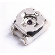


Bourns TC33X-1-104E Trimmer Potentiometer 100 kΩ TC33 Series
Bourns TC33X-1-104E 3.0×3.6 mm single-turn trimmer potentiometer, 100 kΩ, tolerance ±25%, 0.1 W power rating. For on-board bias, reference and zero calibration.
The TC33X-1-104E is a 3.0×3.6 mm surface-mount single-turn trimming potentiometer rated 100 kΩ ±25 % with 0.1 W. Top-face adjustment, continuous rotation, 8 mm tape. In a high-resistance divider it draws only microamps.
Category:Trimmer potentiometer / TC33 系列
Resistance:100 kΩ;Power rating:0.1 W
Specifications
| Parameter | Value |
| Series | TC33 |
| Nominal resistance | 100 kΩ |
| Resistance tolerance | ±25 % |
| Power rating | 0.1 W |
| Turns | Single turn |
| Linearity | — |
| Temperature coefficient | ±250 ppm/℃ |
| Mechanical rotation | — |
| Dimensions | 3.0×3.6 mm |
Other Resistances in This Series
| Model | Resistance | Tolerance | Power |
| TC33X-1-103E | 10 kΩ | ±25 % | 0.1 W |
Product Description
What this product is
The TC33X-1-104E is a 3 mm square surface-mount single turn trimmer, and 100 kΩ is the high end of the series. In a high-resistance divider it draws only microamps, loading the driving stage lightly, while the 3 mm footprint fits the narrowest module cavity.
Dimensions and appearance
Body 3.0×3.6 mm with the adjustment slot on top for the H-90 tool, terminals on both sides, 8 mm tape. The grey area underneath takes cement if the part has to be anchored; the board needs only the 3.0×3.6 mm footprint and pads on both sides.
How it works
The wiper crosses the cermet element over at least 200°, with 100 kΩ held from terminal 1 to 3 and terminal 2 as the wiper. A divider takes its output there. This version rotates continuously, so past either end the wiper idles with no mechanical stop.
How to choose
In the part number, 104 is the resistance code: the first two digits 10 are the significant figures and the third digit 4 means × 10⁴, so 100 kΩ; 103 is 10 kΩ. At 100 kΩ, 0.1 W would allow 100 V, but the 50 V limit caps the voltage. Tolerance ±25 % is ±25 kΩ.
Parameters and documentation
The full datasheet is on page 1 and can be downloaded from this page, with the resistance table, dimensions and tape drawing. Operating range -40 °C to +100 °C, temperature coefficient ±250 ppm/°C, contact resistance variation 5 %. For lot confirmation or an alternative, contact our sales team.
Selection Notes
1. At 100 kΩ the 50 V limit arrives before the power limit
√(0.1 W × 100 kΩ) = 100 V, but the datasheet caps voltage at 50 VDC, so the current is 0.5 mA and only 0.025 W is used. In a high-voltage loop the constraint on this value is voltage, so work the current out from 50 V.
2. ±25 % of 100 kΩ is ±25 kΩ
The ends land between 75 kΩ and 125 kΩ. A divider trims the ratio back, but where the part runs as a two-wire variable resistor in series with a fixed resistor, put that 25 kΩ into the series total instead of using the nominal value.
3. 200° across 100 kΩ leaves 500 Ω per degree
Screwdriver repeatability of 2° to 5° moves the setting by 1 kΩ to 2.5 kΩ, and contact resistance variation of 5 % is 5 kΩ, larger than the adjustment step itself. A hand cannot place that setpoint, so narrow the range with fixed resistors first.