

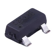


BOURNS CDSOT23-T24CAN-Q TVS Diode 24V SOT-23 CAN Bus ESD Protection
24 V bidirectional TVS array, 36 V clamp, 22 pF line-to-ground, AEC-Q101
The CDSOT23-T24CAN-Q is a dual TVS diode array in a SOT-23 package that handles ESD and surge on both CAN bus lines. Working reverse voltage 24 V, breakdown 26.2–32 V, clamping 36 V at 5 A. Capacitance is 22 pF typ and 30 pF max line to ground, 11 pF line to line. AEC-Q101 qualified, IEC 61000-4-2 contact discharge ±30 kV.
Brand:伯恩斯 BOURNS(集电通授权代理)
Category:TVS Diode / SOT-23
Working voltage 24 V; breakdown 26.2–32 V; clamp 36 V @ 5 A
Specifications
| Item | Value |
| Working reverse voltage | 24 V |
| Breakdown voltage | 26.2–32 V @ 1 mA |
| Clamping voltage at 5 A | 36 V |
| Clamping voltage at 8 A | 40 V |
| Peak pulse current | 8 A(8/20 μs) |
| Peak pulse power | 350 W |
| Capacitance, line to ground | 22 pF typ / 30 pF max |
| Capacitance, line to line | 11 pF typ |
| Reverse leakage | 100 nA max |
| ESD contact discharge | ±30 kV(IEC 61000-4-2) |
| Automotive qualification | AEC-Q101 |
| Package | SOT-23(3 脚) |
Values from Bourns datasheet CDSOT23-T24CAN-Q.pdf, page 1 electrical table and page 3 surge curves. Clamping voltages are for an 8/20 μs waveform.
Product Description
What this product is
It works on voltage. When tens of volts of ESD or a surge arrive on the CAN bus it holds the level around 36 V and the two transceiver bus pins survive. Current is handled separately by a fuse in the supply path, so a board usually carries one of each.
Package and pins
Three-pin SOT-23, body 2.74–3.00 mm long, 1.20–1.40 mm wide and 0.89–1.17 mm high. Pin 1 goes to CAN H, pin 2 to CAN L and pin 3 to ground. It mounts on the industry-standard SOT-23 footprint, with recommended pads 0.95×0.85 mm and the two rows 2.00 mm apart.
How it protects
Above 26.2 V the internal diodes conduct and shunt the excess energy to ground. On an 8/20 μs waveform the part sits at 36 V with 5 A through it and at 40 V with 8 A. Check both clamp values against the bus-pin rating of your chosen transceiver, not just one. most CAN transceivers carry on their bus pins. A 500 V surge puts 5.5 A down each line and clamps below 37 V.
Reading the key ratings
Start with capacitance: 22 pF typ and 30 pF max line to ground, 11 pF line to line, measured at 1 MHz. A bit at 1 Mbit/s lasts 1 μs, and extra capacitance rounds the edges until the waveform distorts and the link errors. Then read the clamp: 36 V at 5 A has to stay inside the transceiver rating.
Parameters and documents
The full datasheet is available for download on this page, with the clamping curve and the breakdown and leakage curves against temperature. The 24 V figure is the continuous working voltage; a CAN bus swings 0–5 V, so the margin is wide, and 24 V miswired onto the bus only breaks the part down above 26.2 V. For lot confirmation or an alternative, contact our sales team.
Selection Notes
1. 22 pF is the number that decides the fit
A bit at 1 Mbit/s lasts 1 μs, and a 22 pF junction capacitance on each line to ground already rounds the edges. This part holds 22 pF typ and 30 pF max, which keeps the effect on high-speed CAN acceptable. A general-purpose TVS at the 100 pF level blunts the same edge until the sample point drifts to the wrong side and the error rate climbs. At 2 Mbit/s for CAN FD a bit lasts 0.5 μs, so work against 30 pF max rather than typ.
2. Read 36 V against the transceiver rating
At 5 A on an 8/20 μs waveform the part sits at 36 V and at 8 A it reaches 40 V. Both clamp values have to line up with the bus-pin rating of the transceiver you use; if they exceed it, choose a different part. A 500 V surge measured below 37 V. Keeping the surge current under 5 A leaves room. Miswired 24 V onto the bus does not break the part down, since conduction starts at 26.2 V, and leakage stays under 100 nA.
3. Placement and ground decide whether it works
The surge arrives at the bus connector, and the longer the trace from there to the part, the more of it the trace inductance and resistance take away, which pushes the clamp point up. Put the part inside the connector with short, straight traces to the two signal lines. A 10 mil, 1 oz trace carries the 5.5 A of a 500 V surge. Take the ground pin to the plane with a short trace and one via; a long ground return raises the clamp voltage.