

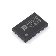


BOURNS TBU-CA065-200-WH High-Speed Protector 200mA DFN
High-speed protector, blocks within 1 μs, 200-400 mA trigger, 650 V withstand
The TBU-CA065-200-WH is a TBU high-speed overcurrent protector, a bidirectional part built on MOSFET technology and wired in series with a signal line. Trigger current is 200 mA min, 300 mA typ and 400 mA max, with the transition to the protected state inside 1 μs. Peak impulse withstand is 650 V for surges under 10 ms, continuous AC 300 V RMS. DFN package 6.50×4.00 mm, three pads, 3000 per reel.
Brand:伯恩斯 BOURNS(集电通授权代理)
Category:Overcurrent Protector TBU / DFN
Trigger current 200–400 mA; blocking time 1 μs; 650 V withstand
Specifications
| Item | Value |
| Trigger current, min | 200 mA |
| Trigger current, typ | 300 mA |
| Trigger current, max | 400 mA |
| Blocking response time | 1 μs max |
| Peak impulse withstand | 650 V(<10 ms) |
| Continuous AC voltage | 300 V RMS |
| On-resistance, min | 8.6 Ω |
| On-resistance, typ | 9.8 Ω |
| Quiescent current | 0.25–1.00 mA |
| Maximum junction temperature | +125 ℃ |
| Thermal resistance, recommended pad | 98 ℃/W |
| Thermal resistance, 6 cm² copper | 40 ℃/W |
| Package | DFN 6.50×4.00 mm(3 pad) |
Values from Bourns series datasheet TBU-CA.pdf, pages 1–2, row CA065-200-WH. That datasheet covers the whole CA025–CA085 family; this page covers one part only.
Product Description
What this product is
It sits in series with a communication or sensor line and handles current. When the current crosses the trigger value it breaks the path and the circuit behind it stays clear of the surge. Once the voltage falls below the reset threshold the part conducts again, so nothing comes off the board. Voice and VDSL cards, process control equipment and test instruments are the usual places for it.
Package and pins
DFN package, body 6.50×4.00 mm and 0.80–1.00 mm high, with three pads. Pads 1 and 3 are the two ends of the line and pass current in either direction; pad 2 has no internal connection, is still soldered down and only spreads heat. Copper added beyond the pads takes junction-to-pad thermal resistance from 98 °C/W to 40 °C/W.
How it protects
Above the trigger current the internal detection circuit acts within 1 μs and holds the line current below the trigger value, so the surge does not reach the protected side. While the voltage stays above the reset threshold the part pulls the current down to a quiescent 0.25–1.00 mA; below the threshold it returns to conduction on its own.
Reading the key ratings
The trigger current comes as a window: below 200 mA the part does not act, above 400 mA it always does, and where inside the band it switches is not guaranteed. A line works when normal current sits well under 200 mA and fault current well over 400 mA. The 650 V figure stops surges; 300 V RMS is what can stay on the line.
Parameters and documents
The full datasheet is available for download on this page, with trigger current, on-resistance and power derating against temperature. Operating range is −55 to +125 °C, and the same family spans 250 V to 850 V and 50 mA to 500 mA in five steps each. For lot confirmation or an alternative, contact our sales team.
Selection Notes
1. A PPTC works on heat, this part on a detection circuit
A PPTC heats, expands and raises its resistance, and its trip time runs from tens of milliseconds to tens of seconds with the fault multiple. This part detects current with a MOSFET circuit and reaches the protected state inside 1 μs, three orders of magnitude faster or better. Communication and sensor lines that cannot sit at high current belong on this part; a supply input with large energy behind it and time to spare suits a PPTC.
2. 8.6 Ω sits in the line, so budget the drop
On-resistance is given as 8.6 Ω min and 9.8 Ω typ, with no maximum column, so work the drop at 9.8 Ω: 0.20 V at 20 mA, 0.98 V at 100 mA and 2.45 V at 250 mA. For analogue signals, 4–20 mA loops and lines that carry power as well, subtract that drop first and confirm the far end still reads what is left. The 500 mA part in the same family measures 7.0 Ω.
3. 650 V lasts 10 ms, 300 V RMS is what stays on the line
The 650 V impulse rating is stated for surges shorter than 10 ms, covering lightning induction and a 220 V mains conductor touching the line, while 300 V RMS is the voltage that can stay on it continuously. Where lightning energy is high, put a MOV or GDT ahead of the part to hold the peak under 650 V. A DC bias above the reset threshold can stop the part from coming back after a surge, so monitor it in software or cycle the supply.