

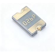


Bourns MF-MSMF020-2 Resettable Fuse 0.20A 30V 1812
0.20 A hold current, 30 V maximum voltage, 1812 (4532) package. Interrupt rating 80 A, the highest among the 30 V parts
The MF-MSMF020-2 is a 1812 surface-mount resettable fuse that carries 0.20 A continuously and withstands 30 V maximum. It measures 4.5 × 3.2 mm, has gold-plated terminals and suits reflow soldering. UL, CSA and TÜV recognised, RoHS compliant. Commonly used for overcurrent protection on 24 V control boards, auxiliary motor-drive circuits and communication ports.
Category:Resettable fuse / SMD, 1812 SMD (4532 mm)
Voltage:30 V; Current:hold 0.2 A; trip 0.4 A.
Specifications
| Parameter | Value |
| Hold current | 0.2 A |
| Trip current | 0.4 A |
| Maximum voltage | 30 V |
| Maximum fault current | 80 A |
| Initial resistance | 0.4 Ω |
| Post-trip max resistance | 6 Ω |
| Trip current / time | 6 A / 0.06 s |
| Dissipated power | 0.8 W |
| Package | 1812 SMD (4532 mm) |
Temperature Derating
| -40℃ | -20℃ | 0℃ | 23℃ | 40℃ | 50℃ | 60℃ | 70℃ | 85℃ | |
| Hold current (A) | 0.29 | 0.26 | 0.23 | 0.2 | 0.17 | 0.15 | 0.14 | 0.12 | 0.1 |
| Share of 23 °C rating | 145% | 130% | 115% | 100% | 85% | 75% | 70% | 60% | 50% |
Same-Package Alternatives
| Model | Vmax | R1max | Package | Note |
| MF-MSMF020/60 | 60 V | 6 Ω | 1812 SMD (4532 mm) |
Product Description
What this product is
The MF-MSMF020-2 is a polymer resettable fuse placed between a supply and its load to limit current. It recovers by itself after a fault, so no board comes out for rework. Its 80 A interrupt rating is the highest in the 30 V group. It suits 24 V rails fed directly from a battery, where fault current can be high.
Dimensions and appearance
1812 package, 4532 in metric, 4.5 mm long, 3.2 mm wide and 0.75 mm high. Gold-plated terminals, black body, model code and production lot marked on top. The 60 V version, suffix /60, fits the same footprint and cannot be told apart by size, so confirm the suffix on the reel label at goods-in.
How it works
It sits in series in the loop. At 0.20 A its own resistance is 0.40 Ω, which gives a drop of 0.08 V. Above 0.40 A the internal material expands with heat, resistance climbs and the current is limited. At a fault current of 6 A it opens within 0.06 s.
After the fault is cleared
When the part cools after a trip, resistance falls back to the low state and the loop runs again with no manual reset. After one trip the resistance is at most 6.00 Ω, 15 times the 0.40 Ω factory value, which gives 1.20 V at 0.20 A. Repeated trips stay within the 6.00 Ω limit; check the downstream circuit against that figure.
Parameters and selection
The full datasheet is available for download on this page, covering the derating table, time-current curves and package dimensions. At 60 °C inside an enclosure the hold current is 0.14 A, and 0.10 A at 85 °C. A 24 V nominal rail reaches 28.8 V, so check the margin against that figure. For lot confirmation or an alternative model, contact our sales team.
Selection Notes
1. 80 A of interrupt capability, half of which the 60 V version gives up
There are two 0.20 A parts in this series: this one at 30 V with an 80 A interrupt rating, and the /60 at 60 V with 40 A. Raising the voltage rating halves the interrupt rating at the same time. Where fault current on a 24 V rail can reach 80 A, specify this 30 V part; where the supply itself limits fault current and 60 V is needed, take the /60. Both ratings belong in the same decision.
2. 30 V leaves 1.2 V of margin on a 24 V rail
A fully charged 24 V battery reaches 28.8 V, which leaves 1.2 V below the 30 V ceiling. A switching transient above that exceeds the rating, and one surge breaks the part down; a broken-down part goes open and the whole board loses power. On a 24 V rail, clamp transients in front of this part, for example with a TVS diode, or move to the /60 for more margin.
3. It opens fast on a short, slowly on a mild overload
At 6 A it opens within 0.06 s; the 0.10 A part in this series needs 1.5 s at 0.5 A. Close to 0.40 A the opening time stretches, so read the time-current curve in the datasheet rather than assuming 0.06 s. A load swinging around 0.30 A already sits near the trip point, so step up one current class.