

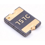


Bourns MF-MSMF075-2 Resettable Fuse 0.75A 13.2V 1812
0.75 A hold current, 13.2 V maximum voltage, 1812 (4532) package. The 13.2 V figure is not arbitrary: it is the float-ch
The MF-MSMF075-2 is a 1812 surface-mount resettable fuse that carries 0.75 A continuously and withstands 13.2 V maximum. It measures 4.5 × 3.2 mm, has gold-plated terminals and suits reflow soldering. UL, CSA and TÜV recognised, RoHS compliant. Commonly used for overcurrent protection on boards fed from a regulated 12 V supply, on display backlights and on USB charging modules.
Category:Resettable fuse / SMD, 1812 SMD (4532 mm)
Voltage:13.2 V; Current:hold 0.75 A; trip 1.5 A.
Specifications
| Parameter | Value |
| Hold current | 0.75 A |
| Trip current | 1.5 A |
| Maximum voltage | 13.2 V |
| Maximum fault current | 100 A |
| Initial resistance | 0.11 Ω |
| Post-trip max resistance | 0.45 Ω |
| Trip current / time | 8 A / 0.2 s |
| Dissipated power | 0.8 W |
| Package | 1812 SMD (4532 mm) |
Temperature Derating
| -40℃ | -20℃ | 0℃ | 23℃ | 40℃ | 50℃ | 60℃ | 70℃ | 85℃ | |
| Hold current (A) | 1.15 | 1.01 | 0.88 | 0.75 | 0.65 | 0.6 | 0.55 | 0.49 | 0.43 |
| Share of 23 °C rating | 153% | 135% | 117% | 100% | 87% | 80% | 73% | 65% | 57% |
Same-Package Alternatives
| Model | Vmax | R1max | Package | Note |
| MF-MSMF075/24 | 24 V | 0.45 Ω | 1812 SMD (4532 mm) |
Product Description
What this product is
The MF-MSMF075-2 is a polymer resettable fuse connected in series between a supply and its load. Above 1.50 A the internal material expands with heat, resistance rises and the current is held to a low value. Once the fault is cleared and the part cools it conducts again, so no board comes out for rework. At 0.75 A it suits fans, relay coils and small motors.
Dimensions and appearance
1812 package, 4532 in metric, 4.5 mm long, 3.2 mm wide and 0.75 mm high. Gold-plated terminals, black body, model code and production lot marked on top. All 18 models in this series fit this one footprint, so a change of model needs no pad revision. Voltage variants share the same body; check the model on the reel label at goods-in.
How it works
It sits in series in the loop. At 23 °C and 0.75 A its own resistance is 0.11 Ω, which gives a drop of 0.08 V, 0.7% of a 12 V supply. Above 1.50 A, or as ambient temperature rises, the internal material expands with heat, resistance climbs and the current is limited. At 8 A it opens within 0.20 s.
After the fault is cleared
When the part cools after a trip, resistance falls back to the low state and the loop runs again with no manual reset. After one trip the resistance is at most 0.45 Ω, four times the 0.11 Ω factory value, which gives 0.34 V at 0.75 A. That 0.34 V sits across the downstream circuit; check that the circuit accepts it.
Parameters and selection
The full datasheet is available for download on this page and covers the derating table, time-current curves and package dimensions. At 60 °C inside an enclosure the hold current is 0.55 A, and 0.43 A at 85 °C; read the table at the highest enclosure temperature. For lot confirmation, stock or a 24 V part in the same current class, contact our sales team.
Selection Notes
1. 13.2 V only holds for a regulated 12 V supply
A 12 V adapter rated ±10% reaches 13.2 V, which is the top of this part's range. A 12 V lead-acid battery reaches 14.4 V while charging, above the rating; the first charge cycle breaks the part down, and a broken-down part goes open and takes the board down. Use the MF-MSMF075/24-2 behind a battery and this part behind an adapter. A 24 V rail is out of reach for it.
2. 0.75 A hold, 1.50 A trip
The gap between the two numbers is a factor of two. Fans, relays and capacitor banks draw three to four times their steady current at switch-on, so a 0.75 A load can pull past 2 A for a moment and this part treats that as a fault. Limit the inrush or step up to the 1.10 A class; measure the start-up peak before choosing.
3. 0.43 A left at 85 °C
The 0.75 A rating applies at 23 °C. At 60 °C inside an enclosure the hold current is 0.55 A, and at 85 °C it is 0.43 A, 57% of rating. A board drawing 0.60 A passes on the bench and opens by itself in a 60 °C enclosure. Calculate the load margin from the derating table at the highest enclosure temperature.