

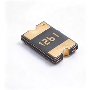


Bourns MF-MSMF125-2 Resettable Fuse 1.25A 6V 1812
1.25 A hold current, 6 V maximum voltage, 1812 (4532) package. The 6 V ceiling confines it to 5 V rails. Post-trip resis
The MF-MSMF125-2 is a 1812 surface-mount resettable fuse that carries 1.25 A continuously and withstands 6 V maximum. It measures 4.5 × 3.2 mm, has gold-plated terminals and suits reflow soldering. UL, CSA and TÜV recognised, RoHS compliant. Commonly used for overcurrent protection on 5 V adaptor outputs, USB ports and 5 V branches inside equipment.
Category:Resettable fuse / SMD, 1812 SMD (4532 mm)
Voltage:6 V; Current:hold 1.25 A; trip 2.5 A.
Specifications
| Parameter | Value |
| Hold current | 1.25 A |
| Trip current | 2.5 A |
| Maximum voltage | 6 V |
| Maximum fault current | 100 A |
| Initial resistance | 0.035 Ω |
| Post-trip max resistance | 0.14 Ω |
| Trip current / time | 8 A / 0.4 s |
| Dissipated power | 0.8 W |
| Package | 1812 SMD (4532 mm) |
Temperature Derating
| -40℃ | -20℃ | 0℃ | 23℃ | 40℃ | 50℃ | 60℃ | 70℃ | 85℃ | |
| Hold current (A) | 1.8 | 1.63 | 1.43 | 1.25 | 1.08 | 0.99 | 0.91 | 0.81 | 0.68 |
| Share of 23 °C rating | 144% | 130% | 114% | 100% | 86% | 79% | 73% | 65% | 54% |
Product Description
What this product is
The MF-MSMF125-2 is a polymer resettable fuse connected in series in a 5 V branch. Above 2.50 A the internal resistance rises and the current is held to a low value. Once the fault is cleared and the part cools, it conducts again, so the board stays in service. At 1.25 A it suits one small board or one USB port.
Dimensions and appearance
1812 package, 4532 in metric, 4.5 mm long, 3.2 mm wide and 0.75 mm high, the same as the other 17 models of this series, so a change of model needs no pad revision. Gold-plated terminals, black body, model code and production lot marked on top. Supplied on tape and reel; hand soldering is also suitable.
How it works
It sits in series in the loop. At 23 °C and 1.25 A its own resistance is 0.035 Ω, which gives a drop of 0.04 V, or 0.8% of a 5 V rail. Above 2.50 A, or as ambient temperature rises, the internal material expands with heat, resistance climbs and the current is limited.
After the fault is cleared
When the part cools after a trip, resistance falls back to the low state and the loop runs again with no manual reset. After one trip the resistance is at most 0.14 Ω, 4 times the 0.035 Ω factory value, which gives 0.18 V at 1.25 A. The 0.14 Ω figure is the limit after repeated trips; check the downstream circuit against it.
Parameters and selection
The full datasheet is available for download on this page, covering the derating table, time-current curves and package dimensions. At 60 °C inside an enclosure the hold current is 0.91 A, and 0.68 A at 85 °C; size the load against those figures. This current class comes in a 6 V version only, so a loop above 6 V needs another class; ask our sales team.
Selection Notes
1. This current class exists in 6 V only
Bourns builds the 1.25 A part at 6 V and at no higher voltage. The 1.10 A class comes in 16 V and 24 V versions and the 1.50 A class in 24 V, while this one has none. A 5 V adaptor reaches 5.5 V at no load, which leaves 0.5 V of margin against the 6 V ceiling; a 12 V or 24 V branch cannot use this part at all. Where 1.25 A is needed above 6 V, step up to the 1.50 A 24 V version or down to the 1.10 A 16 V version, and recalculate the load current.
2. The step from 1.10 A to 1.25 A pays off in resistance
Current rises 0.15 A and the trip point moves from 2.20 A to 2.50 A. The larger change is in resistance after a trip: 0.21 Ω on the 1.10 A part against 0.14 Ω here, so the drop after recovery falls from 0.23 V to 0.18 V at rated current. A load of about 1.1 A where drop matters gains from this step; a load already at 1.3 A should go to the 1.50 A part.
3. The inrush current needs more room than 1.25 A
The 1.25 A figure is the continuous current; the trip point is 2.50 A. Capacitors on a board charge at switch-on and the current often passes 2 A, and a warm enclosure shortens the time it takes to trip. A board that draws 1.1 A continuously but carries large capacitance trips this part at switch-on. Check the inrush peak and leave margin; where the peak approaches 2.5 A, step up to the 1.50 A part.