

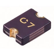


Bourns MF-MSMF250/16X-2 Resettable Fuse 2.50A 16V 1812
2.50 A hold current, 16 V maximum voltage, 1812 (4532) package. It retains only 38% of rating at 85 °C — among the steep
The MF-MSMF250/16X-2 is a 1812 surface-mount resettable fuse that carries 2.50 A continuously and withstands 16 V maximum. It measures 4.5 × 3.2 mm, has gold-plated terminals and suits reflow soldering. UL, CSA and TÜV recognised, RoHS compliant. The 100 A interrupt rating lets it break a heavy fault current safely. Commonly used for overcurrent protection on 12 V motor drives, cooling fans and high-current charging ports.
Category:Resettable fuse / SMD, 1812 SMD (4532 mm)
Voltage:16 V; Current:hold 2.5 A; trip 5 A.
Specifications
| Parameter | Value |
| Hold current | 2.5 A |
| Trip current | 5 A |
| Maximum voltage | 16 V |
| Maximum fault current | 100 A |
| Initial resistance | 0.015 Ω |
| Post-trip max resistance | 0.1 Ω |
| Trip current / time | 8 A / 5 s |
| Dissipated power | 1.2 W |
| Package | 1812 SMD (4532 mm) |
Temperature Derating
| -40℃ | -20℃ | 0℃ | 23℃ | 40℃ | 50℃ | 60℃ | 70℃ | 85℃ | |
| Hold current (A) | 3.9 | 3.42 | 2.96 | 2.5 | 2.24 | 1.98 | 1.85 | 1.29 | 0.94 |
| Share of 23 °C rating | 156% | 137% | 118% | 100% | 90% | 79% | 74% | 52% | 38% |
Product Description
What this product is
The MF-MSMF250/16X-2 is a polymer resettable fuse connected in series between a supply and its load to limit current. It recovers by itself after a fault, so the board stays in the enclosure. A 16 V rating with a 100 A interrupt rating is offered only by this part in the 2.50 A class. It suits 12 V rails fed straight from a battery, where fault current is high.
Dimensions and appearance
1812 package, 4532 in metric, 4.5 mm long and 3.2 mm wide. Gold-plated terminals, black body, model code and production lot marked on top. The outline matches the other 1812 parts in the series, so the voltage rating is told apart by the body marking and the reel label; check the label for the /16X suffix when changing reels.
How it works
It sits in series in the loop. At 23 °C and 2.50 A its own resistance is 0.015 Ω, a drop of 0.04 V, which is 0.3% of a 12 V rail and leaves nearly the whole supply to the load. Above 5.00 A the internal material expands with heat, resistance rises sharply and the loop current is held down.
After the fault is cleared
When the part cools after a trip, resistance falls back to the low state and the loop runs again with no manual reset. The post-trip resistance is at most 0.10 Ω, 6.7 times the 0.015 Ω factory value, which gives 0.25 V at 2.50 A. On a 12 V rail that 0.25 V is 2% of the supply; check the downstream circuit against that figure.
Parameters and selection
The full datasheet is available for download on this page, covering the derating table, time-current curves and package dimensions. At 60 °C inside an enclosure the hold current falls to 1.85 A, and to 0.94 A at 85 °C; size the load from the column at the highest enclosure temperature. For lot confirmation, stock or an alternative model, contact our sales team.
Selection Notes
1. The larger part carries less at 85 °C
The 2.00 A part still holds 1.25 A at 85 °C, while this one rated 2.50 A holds 0.94 A at the same temperature, 0.31 A less. High-temperature hold is 38% here against 63% on the 2.00 A part. Ranking parts by rated current picks the wrong one once the enclosure runs warm. Fix the maximum enclosure temperature first, then compare the numbers in that column of the derating table.
2. The 16 V rating costs resistance after a trip
The post-trip limit is 0.10 Ω, 25% above the 0.080 Ω of the 2.00 A part. Holding 16 V takes a thicker element, and the resistance rises with it, which is 0.25 V at 2.50 A. On a board that is sensitive to voltage drop, add that difference to the supply margin before moving up from the 2.00 A part.
3. A 8 A fault takes up to 5 s to clear
The datasheet trip time is 5 s maximum at 8 A, where the 2.00 A part needs 3 s at the same current. Just above 5.00 A the opening time stretches further, so read the time-current curve rather than assuming 5 s. Where this fuse protects a MOSFET, confirm the device survives the heating over those 5 s.