

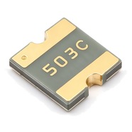


Bourns MF-SMDF050 Resettable Fuse 0.55A 60V 2018 SMD
Bourns MF-SMDF050 SMD resettable fuse, 0.55 A hold current, 60 V maximum voltage, 2018 package. Self-resetting after the fault is cleared, no replacement needed.
The MF-SMDF050 is a 2018 surface-mount resettable fuse that carries 0.55 A continuously and withstands 60 V maximum. The body measures 4.72–5.44 mm long, 4.22–4.93 mm wide and 0.79–1.09 mm high, with gold-plated terminals for reflow soldering. UL, CSA and TÜV recognised, RoHS compliant. Commonly used for overcurrent protection on PoE ports, the low-voltage side of telecom equipment and automotive control modules.
Category:Resettable fuse / SMD, 2018 SMD (5045 mm)
Voltage:60 V; Current:hold 0.55 A; trip 1.2 A.
Specifications
| Parameter | Value |
| Hold current | 0.55 A |
| Trip current | 1.2 A |
| Maximum voltage | 60 V |
| Maximum fault current | 10 A |
| Initial resistance | 0.2 Ω |
| Post-trip max resistance | 1 Ω |
| Trip current / time | 2.5 A / 3 s |
| Dissipated power | 0.9 W |
| Package | 2018 SMD (5045 mm) |
Temperature Derating
| -40℃ | -20℃ | 0℃ | 23℃ | 40℃ | 50℃ | 60℃ | 70℃ | 85℃ | |
| Hold current (A) | 0.87 | 0.77 | 0.67 | 0.55 | 0.46 | 0.41 | 0.36 | 0.31 | 0.23 |
| Share of 23 °C rating | 158% | 140% | 122% | 100% | 84% | 75% | 65% | 56% | 42% |
Product Description
What this product is
The MF-SMDF050 is a polymer resettable fuse wired in series between a supply and its load. Its 60 V rating is the highest of the three models in this series, the others being 15 V and 10 V, so it suits buses that run at 48 V or feed PoE. The part opens as the internal material expands with heat and recovers by itself once the fault is cleared and the part cools.
Dimensions and appearance
2018 package, 5045 in metric, body 4.72–5.44 mm long, 4.22–4.93 mm wide and 0.79–1.09 mm high. All three models share this footprint and differ in height; at 0.79–1.09 mm this 0.55 A part is the thickest. Nickel-plated terminals with a gold finish, four characters marked on top, the first two the model code 50. Supplied on 16 mm tape, 6000 parts per reel.
How it works
It sits in series in the loop. At 0.55 A its own resistance is 0.200 Ω, which gives a drop of 0.11 V. Above 1.20 A the internal material expands with heat, resistance climbs and the current is held to a low value. At a fault current of 2.5 A it opens within 3.0 s.
After the fault is cleared
When the part cools after a trip, resistance falls back to the low state and the loop runs again with no manual reset. After one trip the resistance is at most 1.0 Ω, five times the 0.200 Ω factory value, which gives 0.55 V at 0.55 A. That 0.55 V appears across the downstream circuit, so a 5 V module fed from the 60 V bus behind this part needs rechecking.
Parameters and selection
The full datasheet is available for download on this page and covers the derating table, time-current curves and package dimensions. At 60 °C inside an enclosure the hold current is 0.36 A, and 0.23 A at 85 °C; size the load against those figures. A 48 V telecom supply produces surges above 60 V, so clamp them ahead of this part. For lot confirmation or an alternative, contact our sales team.
Selection Notes
1. 60 V of standoff, only 10 A of interrupt
The 10 A interrupt rating means the part clears a fault at 60 V as long as the available fault current stays under 10 A. Fault current on a 48 V telecom bus or at a PoE port often runs higher; above 10 A the part may arc as it opens, suffer damage and leave the fault unprotected. Calculate the maximum available fault current first, then limit it ahead of the part or move to a higher interrupt rating.
2. At -40 °C the hold current rises to 0.87 A
The derating table gives 0.87 A at -40 °C, 58 % above the 0.55 A rating at 23 °C. In the cold the polymer is stiffer, so the same current heats it less and the trip point moves up along with the hold current. On outdoor equipment in winter or an automotive cold start, a genuine fault keeps conducting for longer before the part opens. The table gives hold current only; read trip time from the time-current curve.
3. A 2.5 A fault takes 3.0 s to clear
At 2.5 A, 4.5 times the hold current, the part takes up to 3.0 s to open. For those 3 s the fault keeps drawing 2.5 A, and the traces, connectors and protected devices downstream have to take that current. On a 60 V bus the supply delivers 150 W throughout. Where the overload is a small multiple of the rating it opens even more slowly, so read the time-current curve rather than assuming 3.0 s.