

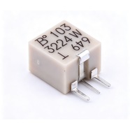


Bourns 3224W-1-103E Trimmer Potentiometer 10 kΩ 3224 Series
Bourns 3224W-1-103E 4.0×4.0×2.5 mm 12-turn trimmer potentiometer, 10 kΩ, tolerance ±10%, 0.25 W power rating. For on-board bias, reference and zero calibration.
The 3224W-1-103E is a 4.0×4.0×2.5 mm surface-mount multiturn trimming potentiometer rated 10 kΩ ±10 % with 12 turns end to end and 0.25 W. Cermet element, flat-blade adjustment slot in the centre of the top face, reflow-solderable terminals. Used for bias and reference dividers that are set once and checked occasionally.
Category:Trimmer potentiometer / 3224 系列
Resistance:10 kΩ;Power rating:0.25 W
Specifications
| Parameter | Value |
| Series | 3224 |
| Nominal resistance | 10 kΩ |
| Resistance tolerance | ±10 % |
| Power rating | 0.25 W |
| Turns | 12 turns |
| Linearity | — |
| Temperature coefficient | ±100 ppm/℃ |
| Mechanical rotation | 4320 ° |
| Dimensions | 4.0×4.0×2.5 mm |
Other Resistances in This Series
| Model | Resistance | Tolerance | Power |
| 3224W-1-102E | 1 kΩ | ±10 % | 0.25 W |
| 3224W-1-502E | 5 kΩ | ±10 % | 0.25 W |
Product Description
What this product is
The 3224W-1-103E is a surface-mount multiturn trimmer that sets the voltage or current at a calibration point. Twelve turns split the 10 kΩ full scale into 12 steps of 833 Ω, fine enough to land the output within millivolts. Bias rails, voltage references and sensor zero points use it.
Dimensions and appearance
Body 4.0×4.0×2.5 mm, surface-mount terminals on both ends sitting on the pads, footprint to the EIA 4 mm trimmer pattern. The slot in the top face is 0.6 mm wide and 0.5 mm deep and takes the H-91 tool. The 103 code and date code are marked on top; tape is 16 mm wide.
How it works
The wiper crosses the cermet element over 12 turns. Resistance from terminal 1 to 2 falls as the shaft turns and terminal 2 to 3 rises by the same amount, so a divider taps the voltage at terminal 2. The 10 kΩ splits into 833 Ω per turn, and the wiper idles past either end without damage.
How to choose
In the part number, 103 is the resistance code: the first two digits 10 are the significant figures and the third digit 3 means × 10³, so 10 kΩ; 102 is 1 kΩ. At 10 kΩ, 0.25 W allows 50 V at 5 mA. Tolerance ±10 % is ±1 kΩ, which a divider circuit trims back out.
Parameters and documentation
The full datasheet is on page 1 and can be downloaded from this page, with electrical characteristics, environmental tests, outline dimensions and tape drawings. Operating range -65 °C to +150 °C, temperature coefficient ±100 ppm/°C, contact resistance variation 1 %. For lot confirmation or a tighter tolerance grade, contact our sales team.
Selection Notes
1. At 10 kΩ the 0.25 W rating tops out at 50 V
√(0.25 W × 10 kΩ) = 50 V at 5 mA. A 12 V bias rail draws 1.2 mA through 10 kΩ, 0.014 W, more than ten times inside the rating. Dividing a 48 V bus with 10 kΩ in the upper leg draws 4.8 mA at 0.23 W, right at the limit, so move to 20 kΩ where the enclosure runs hot.
2. Twelve turns across 10 kΩ leaves 833 Ω per turn
One degree is 2.3 Ω. Contact resistance variation of 1 % is 100 Ω, about 43° of rotation, and that is the jitter seen on the divider output. Behind a stage with 100× gain, 10 mV of jitter at the tap becomes 1 V at the output, so settle that question before ordering a tighter grade.
3. Sealed for board wash, but dry it before adjusting
The part is sealed to survive board washing, though the 0.5 mm deep adjustment slot still holds wash liquid afterwards. Blow it dry before the screwdriver goes in: adjusting wet carries liquid into the cermet element, and the calibration drifts again a few days later.