

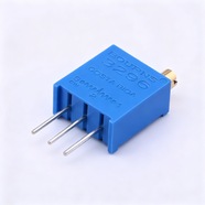


Bourns 3296W-1-103LF Trimmer Potentiometer 10 kΩ 3296 Series
Bourns 3296W-1-103LF 9.53×9.53×4.83 mm 25-turn trimmer potentiometer, 10 kΩ, tolerance ±10%, 0.5 W power rating. For on-board bias, reference and zero calibration.
The 3296W-1-103LF is a 9.53×9.53×4.83 mm through-hole multiturn trimming potentiometer rated 10 kΩ ±10 % with 25 turns and 0.5 W. Flat-blade slot on the top face, three pins on a 2.54 mm pitch, and the LF suffix marks the 100 % tin-plated RoHS version. A common choice for calibration points in industrial equipment.
Category:Trimmer potentiometer / 3296 系列
Resistance:10 kΩ;Power rating:0.5 W
Specifications
| Parameter | Value |
| Series | 3296 |
| Nominal resistance | 10 kΩ |
| Resistance tolerance | ±10 % |
| Power rating | 0.5 W |
| Turns | 25 turns |
| Linearity | — |
| Temperature coefficient | ±100 ppm/℃ |
| Mechanical rotation | 9000 ° |
| Dimensions | 9.53×9.53×4.83 mm |
Other Resistances in This Series
| Model | Resistance | Tolerance | Power |
| 3296W-1-502LF | 5 kΩ | ±10 % | 0.5 W |
| 3296W-1-203LF | 20 kΩ | ±10 % | 0.5 W |
| 3296W-1-202LF | 2 kΩ | ±10 % | 0.5 W |
Product Description
What this product is
The 3296 is a 3/8 inch square multiturn trimmer with through-hole pins, adjusted from the top face after soldering. Twenty-five turns across 10 kΩ leave 400 Ω per turn, fine enough to place an output very precisely. Supply voltage setting, sensor bias and op-amp offset are its usual jobs.
Dimensions and appearance
Square body 9.53×9.53×4.83 mm with a flat-blade slot 0.76 mm wide and 0.56 mm deep, driven by the H-90 tool. Three pins 0.51 mm in diameter on a 2.54 mm pitch in one row, soldered through the board. The top face carries the brand, resistance code, wiring diagram and date code.
How it works
Terminals 1 and 3 are the two ends of the cermet element, terminal 2 is the wiper. An internal lead screw drives the wiper through 25 turns, and past either end it idles, so over-turning does no harm. As a divider, the 1-2 and 2-3 resistances move in opposite directions and the tap follows the angle.
How to choose
In the part number, 103 is the resistance code: the first two digits 10 are the significant figures and the third digit 3 means × 10³, so 10 kΩ; 202 is 2 kΩ. At 10 kΩ, 0.5 W allows 70.7 V at 7.07 mA. Tolerance ±10 % is ±1 kΩ, trimmed back out in a divider.
Parameters and documentation
The full datasheet is on page 1 and can be downloaded from this page, with the resistance table, environmental tests, outline and tape dimensions. Operating range -55 °C to +125 °C, temperature coefficient ±100 ppm/°C, power derating linearly from 0.5 W at 70 °C to 0 W at 125 °C. For a tolerance grade or packaging option, contact our sales team.
Selection Notes
1. The 0.5 W rating applies at 70 °C, derate inside an enclosure
The datasheet gives two points, 0.5 W at 70 °C and 0 W at 125 °C. Interpolating linearly leaves 0.36 W at 85 °C and 0.18 W at 105 °C. Across 10 kΩ that 0.36 W allows only 60 V at 6 mA, so size the divider legs against that figure.
2. Twenty-five turns across 10 kΩ leaves 400 Ω per turn
One degree is 1.1 Ω. Contact resistance variation of 1 % is 100 Ω, about 90° of rotation, and that jitter stays on the tap voltage after the setting is made. The higher the gain of the stage behind it, the more visible it becomes.
3. The top face shows the wiring diagram, so watch terminals 1 and 3
Swapping terminals 1 and 3 does not change the total resistance, but the tap voltage then runs the other way, falling as the shaft turns clockwise. Before adjusting, check the top-face diagram against the 1 and 3 marks on the silkscreen; a reversed part needs the whole range redone.