

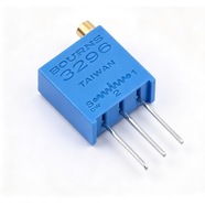


Bourns 3296W-1-203LF Trimmer Potentiometer 20 kΩ 3296 Series
Bourns 3296W-1-203LF 9.53×9.53×4.83 mm 25-turn trimmer potentiometer, 20 kΩ, tolerance ±10%, 0.5 W power rating. For on-board bias, reference and zero calibration.
The 3296W-1-203LF is a 9.53×9.53×4.83 mm through-hole multiturn trimming potentiometer rated 20 kΩ ±10 % with 25 turns and 0.5 W. Top-face flat-blade slot, three pins on a 2.54 mm pitch, LF for the 100 % tin-plated version. Used in high-resistance dividers where the load on the driving stage has to stay light.
Category:Trimmer potentiometer / 3296 系列
Resistance:20 kΩ;Power rating:0.5 W
Specifications
| Parameter | Value |
| Series | 3296 |
| Nominal resistance | 20 kΩ |
| Resistance tolerance | ±10 % |
| Power rating | 0.5 W |
| Turns | 25 turns |
| Linearity | — |
| Temperature coefficient | ±100 ppm/℃ |
| Mechanical rotation | 9000 ° |
| Dimensions | 9.53×9.53×4.83 mm |
Other Resistances in This Series
| Model | Resistance | Tolerance | Power |
| 3296W-1-103LF | 10 kΩ | ±10 % | 0.5 W |
| 3296W-1-502LF | 5 kΩ | ±10 % | 0.5 W |
| 3296W-1-202LF | 2 kΩ | ±10 % | 0.5 W |
Product Description
What this product is
The 3296W-1-203LF is a through-hole multiturn trimmer. At 20 kΩ the 25 turns give 800 Ω per turn. High-resistance loops use it because the divider itself draws little current and loads the preceding stage lightly, while keeping both range and fine adjustment. Meter front ends and sampling dividers are typical.
Dimensions and appearance
Square body 9.53×9.53×4.83 mm, top slot 0.76 mm wide and 0.56 mm deep for the H-90 tool. Three pins 0.51 mm in diameter on a 2.54 mm pitch, through-hole soldered. The top face carries the brand, the 203 code, the wiring diagram and the date code; tubes hold 50 pcs.
How it works
The wiper crosses the cermet element in 25 turns, 800 Ω per turn at 20 kΩ. Resistances 1-2 and 2-3 move in opposite directions, so a divider tap follows the shaft angle. Past either end the wiper idles and nothing jams.
How to choose
In the part number, 203 is the resistance code: the first two digits 20 are the significant figures and the third digit 3 means × 10³, so 20 kΩ; 103 is 10 kΩ. At 20 kΩ, 0.5 W allows 100 V at 5 mA. Tolerance ±10 % is ±2 kΩ, or 2.5 turns of adjustment.
Parameters and documentation
The full datasheet is on page 1 and can be downloaded from this page, with the resistance table, environmental tests, outline and tape dimensions. Operating range -55 °C to +125 °C, temperature coefficient ±100 ppm/°C. For lot confirmation or another value in the series, contact our sales team.
Selection Notes
1. At 20 kΩ the 0.5 W rating needs 100 V to reach
√(0.5 W × 20 kΩ) = 100 V at 5 mA. On a 24 V loop 20 kΩ draws 1.2 mA for 0.029 W, so power is not the constraint here. What matters on this value is the divider ratio and the leakage current; choosing it on power alone gets the wrong part.
2. Twenty-five turns across 20 kΩ leaves 800 Ω per turn
One degree is 2.2 Ω. Contact resistance variation of 1 % is 200 Ω, about 90° of rotation, ten times coarser than the 1 kΩ part. Where a setpoint has to be fine, run the adjustment margin through the 10 kΩ value first.
3. At 20 kΩ work out leakage before anything else
The datasheet gives 1,000 MΩ insulation resistance, so 0.1 μA leaks at 100 V. Across the 20 kΩ full scale, 100 V drives only 5 mA, which puts that leakage at 0.002 %. Insulation resistance falls as the enclosure heats, so check it on measured data above 85 °C.