

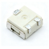


Bourns 3314J-1-103LF Trimmer Potentiometer 10 kΩ 3314 Series
Bourns 3314J-1-103LF 4.5×4.5×2.55 mm single-turn trimmer potentiometer, 10 kΩ, tolerance ±20%, 0.25 W power rating. For on-board bias, reference and zero calibration.
The 3314J-1-103LF is a 4.5×4.5×2.55 mm surface-mount single-turn trimming potentiometer rated 10 kΩ ±20 % with 0.25 W. Top-face adjustment, J-hook terminals, 500 pcs per reel, suited to boards that are reflowed first and calibrated afterwards.
Category:Trimmer potentiometer / 3314 系列
Resistance:10 kΩ;Power rating:0.25 W
Specifications
| Parameter | Value |
| Series | 3314 |
| Nominal resistance | 10 kΩ |
| Resistance tolerance | ±20 % |
| Power rating | 0.25 W |
| Turns | Single turn |
| Linearity | — |
| Temperature coefficient | ±100 ppm/℃ |
| Mechanical rotation | 240 ° |
| Dimensions | 4.5×4.5×2.55 mm |
Other Resistances in This Series
| Model | Resistance | Tolerance | Power |
| 3314J-1-102E | 1 kΩ | ±20 % | 0.25 W |
| 3314G-1-103LF | 10 kΩ | ±20 % | 0.25 W |
Product Description
What this product is
The 3314 is a 4 mm square surface-mount single turn trimmer occupying 20 mm², used for one-time calibration on tightly packed boards: module output trimming, LED current setting, sensor zero. The board can still go through washing afterwards, with no hand-soldered parts left on it.
Dimensions and appearance
Body 4.5×4.5×2.55 mm, flat-blade slot 2.45 mm long, 0.51 mm wide and 0.51 mm deep for the H-90 tool. The J-hook terminals bend down and curl back under the body, landing on the pads for reflow. Resistance code and date code are marked on top.
How it works
The wiper reaches either end in 210° of rotation against a 240° mechanical angle, the remaining 30° being idle travel. Terminals 1 and 3 are the ends of the element and terminal 2 is the wiper, so a divider taps terminal 2 and the angle tracks the output roughly linearly. The ±20 % applies to full scale.
How to choose
In the part number, 103 is the resistance code: the first two digits 10 are the significant figures and the third digit 3 means × 10³, so 10 kΩ; 102 is 1 kΩ. At 10 kΩ, 0.25 W allows 50 V at 5 mA. Tolerance ±20 % is ±2 kΩ, enough where the part is set once and left alone.
Parameters and documentation
The full datasheet is on page 1 and can be downloaded from this page, with the resistance table, environmental tests, dimensions for both the J and G terminals, and tape drawings. Operating range -55 °C to +125 °C, temperature coefficient ±100 ppm/°C, rotational life 100 full cycles. For terminal style confirmation, contact our sales team.
Selection Notes
1. ±20 % is ±2 kΩ, trimmed out by adjustment
A 10 kΩ part can land anywhere between 8 kΩ and 12 kΩ. A divider uses the ratio only, so the adjustment brings the tap back to target; used as a two-wire variable resistor, the missing 2 kΩ shortens the range and the setpoints have to be recalculated.
2. 210° across 10 kΩ leaves 47.6 Ω per degree
Screwdriver repeatability of 2° to 5° moves the setting by 95 Ω to 238 Ω. The 0.25 W rating on 10 kΩ allows 50 V at 5 mA, and above 50 V the element is what fails first.
3. The J-hook solder joint hides under the body
After reflow the joint sits behind the body and visual inspection cannot see it, so checking relies on X-ray or a pull test. Where the joint has to be visible, choose the G style with gull-wing terminals and its fillets on both sides.