

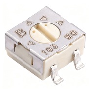


Bourns 3314G-1-103LF Trimmer Potentiometer 10 kΩ 3314 Series
Bourns 3314G-1-103LF 4.5×4.5×2.55 mm single-turn trimmer potentiometer, 10 kΩ, tolerance ±20%, 0.25 W power rating. For on-board bias, reference and zero calibration.
The 3314G-1-103LF is a 4.5×4.5×2.55 mm surface-mount single-turn trimming potentiometer rated 10 kΩ ±20 % with 0.25 W. Top-face adjustment, gull-wing terminals with the joints visible from the side, 500 pcs per reel.
Category:Trimmer potentiometer / 3314 系列
Resistance:10 kΩ;Power rating:0.25 W
Specifications
| Parameter | Value |
| Series | 3314 |
| Nominal resistance | 10 kΩ |
| Resistance tolerance | ±20 % |
| Power rating | 0.25 W |
| Turns | Single turn |
| Linearity | — |
| Temperature coefficient | ±100 ppm/℃ |
| Mechanical rotation | 240 ° |
| Dimensions | 4.5×4.5×2.55 mm |
Other Resistances in This Series
| Model | Resistance | Tolerance | Power |
| 3314J-1-103LF | 10 kΩ | ±20 % | 0.25 W |
| 3314J-1-102E | 1 kΩ | ±20 % | 0.25 W |
Product Description
What this product is
The 3314G and 3314J are the same 4 mm square surface-mount single turn trimmer in two terminal versions: same adjustment face, resistance and power, different lead shape and different visibility of the solder joint. The G style spreads its leads outward, leaving the fillets on both sides.
Dimensions and appearance
Body 4.5×4.5×2.55 mm. The gull-wing leads leave the sides, bend down and lie flat on the pads, taking slightly more footprint than the J style. The top slot is 2.45 mm long, 0.51 mm wide and 0.51 mm deep and shares the H-90 tool with the J style.
How it works
The wiper reaches either end in 210° of rotation against a 240° mechanical angle, the remaining 30° being idle travel. Terminals 1 and 3 are the element ends, terminal 2 is the wiper, so a divider taps terminal 2 and the angle tracks the output roughly linearly.
How to choose
In the part number, 103 is the resistance code: the first two digits 10 are the significant figures and the third digit 3 means × 10³, so 10 kΩ; 102 is 1 kΩ, and LF marks 100 % tin plating. At 10 kΩ, 0.25 W allows 50 V at 5 mA, with ±20 % tolerance.
Parameters and documentation
The full datasheet runs from page 1 to page 3 and can be downloaded from this page, with the resistance table, environmental tests, gull-wing dimensions and tape drawings. Operating range -55 °C to +125 °C, temperature coefficient ±100 ppm/°C, rotational life 100 full cycles.
Selection Notes
1. Gull-wing joints sit in the open, so AOI can judge them
The G style lays its lead ends on the pads and leaves a fillet along the side of the body, which visual inspection and AOI can both read; the J style hides its joints under the body, leaving X-ray as the only check. Production boards that run AOI should take the G.
2. At 10 kΩ the 0.25 W rating stops at 50 V
√(0.25 W × 10 kΩ) = 50 V at 5 mA. A 24 V loop draws 2.4 mA for 0.058 W, four times inside the rating; the same 10 kΩ on a 72 V bus draws 7.2 mA for 0.52 W, twice the rating.
3. Mechanical angle 240°, usable 210°, 30° of idle travel
Wound to the stop, the wiper idles, so touch cannot tell a real end from idle travel. Confirm the end value with a meter: with terminals 1 and 2 at minimum the reading still shows 100 Ω of end resistance, 1 % of full scale.